Item7Appendix2SupportingStatement20190289DET
CAIRNGORMS NATIONAL PARK AUTHORITY Planning Committee Agenda Item 7 Appendix 2 15/11/2019
AGENDA ITEM 7
APPENDIX 2
2019/0289/DET
SUPPORTING STATEMENT
1504 ARCHITEctural & BUILDING CONSULTANCY Bishops Well Cottage Dalguise Dunkeld Perthshire PH8 0JX
SUPPORTING STATEMENT
Client — Mr F Laing
Site Address — Glenbeg Estate, Grandtown On Spey, Moray, PH26 3NT Farm Code — 586⁄0169
Project – Upgrade of existing private ways for forestry & agriculture (In retrospect)
Background
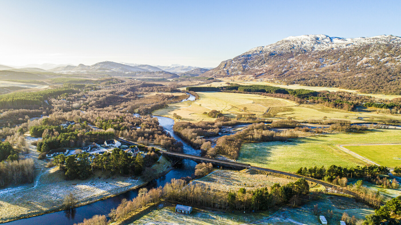
Glenbeg estate extends to approximately 4,000 acres (1620 hectares) and is made up of a mixture of let mixed farming, birch woodland, commercial woodland, amenity woodland and heather hill. There is an arterial estate road which runs through the ground of approximately two miles length. The applicant is seeking approval for the upgrade of 2no existing tracks which are not visible on Ordnance Survey maps but have been have been in use since prior to 1980 by the current landowner, mainly for moving and feeding livestock but also for the maintenance and management of the extensive woodland/forest areas on the estate. Over a period time these particular tracks have become eroded and unsuitable for vehicle movement into these areas of the estate, therefore formal upgrades have been deemed necessary that will allow such operations as timber extraction and livestock movements to continue without further risk to the surrounding landscape and environment.
Map Of Glenbeg Estate, Grandtown On Spey Boundary — Blue. Woodland/Forest — Green Shaded Areas
Image of Upgraded Private Way — Glenbeg Estate
Description
Track A
Grid ref start NJ 00549 28904, Eastings 300550, Northings 828904, Lat 57.339768, Long ‑3.6538768 Grid ref finish NJ 00291 28952, Eastings 300291, Northings 828952, Lat 57.340139 Long ‑3.6581898
Running in a mostly east – west direction adjacent to the Glenbeg Burn. Track A is approximately 311m long with an overall ascent of approx 30m. There are 2no existing natural ford crossings of the burn in the western half of the track with a turning head at the western termination, allowing for articulated timber vehicles to turn freely in a forward gear. Access and egress points to the burn are to be perpendicular to the watercourse where practicable with minimal gradients to the embankments.
Section of existing Track A — Adjacent to Glenbeg Burn
Track B
Grid ref start NJ01313 26773, Eastings 301313, Northings 826773, Lat 57.320796, Long ‑3.6403477 Grid ref finish NJ 01280 27111, Eastings 301280, Northings 827111, Lat 57.323820, Long ‑3.6410344
Running south – north from a watercourse south of Glenbeg House to the west of Wester Graggan, where a formal track terminates on the south side of the burn. Track B is approx 650m long with an overall ascent of approx 2m, it then terminates to the north where it meets the boundary of an existing field.
Northern Section of Track B — through woodland
Justification
Improvements to the existing tracks will allow for the continued movement of livestock within the estate and also assist in the extraction of timber from the woodland. The old tracks were historically never formally constructed as such, with no adequate provision of drainage and the surfaces were in a very in a poor unsustainable condition. The improvements made will allow 4 x4 vehicles and tractors/logging vehicles to continue to use these tracks without further damage to the adjacent landscape and environment.
Methods of Construction
The guidelines as set out by Scottish Natural Heritages Constructed Tracks in the Scottish Highlands (2015 edition), also Good Practise in Design, Construction & Use of floating roads in Peat (Aug 2010) and SEPA advise on Pollution Prevention and Environmental management. Flood risk, surface water drainage and water engineering works. Borrow pits and Restoration and habitat enhancement are to be followed during the planning, design and construction phase of the works. Reference should also be made to ‘The design and use of the structural pavement of unsealed roads 2014’. Works to repair and improve the track would require the use of a 13 tonne tracked excavator to minimise wheel markings and assist compaction, an 8 tonne tracked dumper for use constructing the floating roads, and a 10 tonne wheeled dumper and a vibrating roller. A stone crusher may be required on a loader for grading material onsite. All plant and vehicles will be refuelled using on board pumps from bunded grab tanks to eliminate the risk of spills. A spill kit will be carried on site at all times. For the most part of this existing track material will be obtained from ‘winning’ on site, from shallow borrow pits which run parallel to the upper most side of the track. This method efficiently removes the requirement for hauling large quantities of imported material long distances into the site.
Typical Track construction Example 1.
Typical Track Construction Example 2.
Road crossing Culverts may have to be installed at various locations to take draining water away from the uppers side of the tracks. These will be placed at existing surface water crossings to improve and maintain the surface of the track by the use of large diameter piping. Twin walled pipe at either 450 or 600mm diameter with silt trap and splash stone detailing at each ingress and outlet. All carefully uplifted turfs will be laid aside for reinstatement onto bare surfaces to encourage regrowth. Parallel borrow pit drainage crossings will be installed at max 150m centres at locations to suit the existing topography.
Typical Culvert Inlet
Typical Culvert Outlet
Any/all Floating roads constructions to be carried out over the 2no sections of track identified, should as set out in the SNH /Forestry Commission good practise guidance for Floating Roads on Peat.
No works shall take place within the existing burns at the ford crossing, any necessary works to existing embankments shall be worked backwards from the water line. At no point will plant or machinery work from within the watercourses. Silt netting to be installed where necessary to prevent debris entering the watercourse.
Proposed Materials • Onsite materials won from parallel borrow pits; generally all won, graded and worked within the circumference of the excavator. • Larger boulders brought up and laid aside for use at watercourse culverts. • Culverts — large diameter twin wall plastic pipe.
Design — Associated Documents • 1:10000 location plan • 1:7500 site plan – inc delineation of the track and areas of specific features • 1:2500 block plan track A • 1:2500 block plan track B • Construction Detail – Typical profile of repair to existing track inc. shallow borrow pit channel • Construction Detail – Road crossing culvert from parallel borrow pit drain • Horizontal & vertical profiles of Track A • Horizontal & vertical profiles of Track B


